

Input Shaft Kit, 35-Spline Heavy-Duty
Chrysler 47RH - 48RE
D121-104-G35SK
Limited Supply
Pricing:
$1,699.00
Description
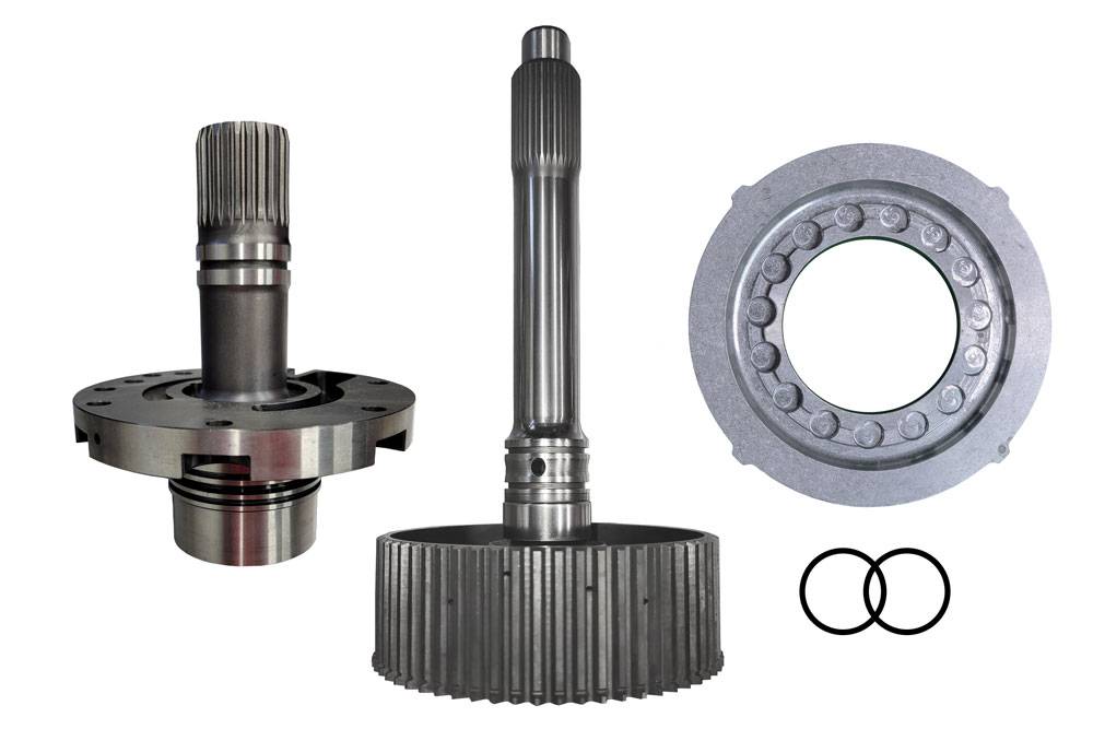
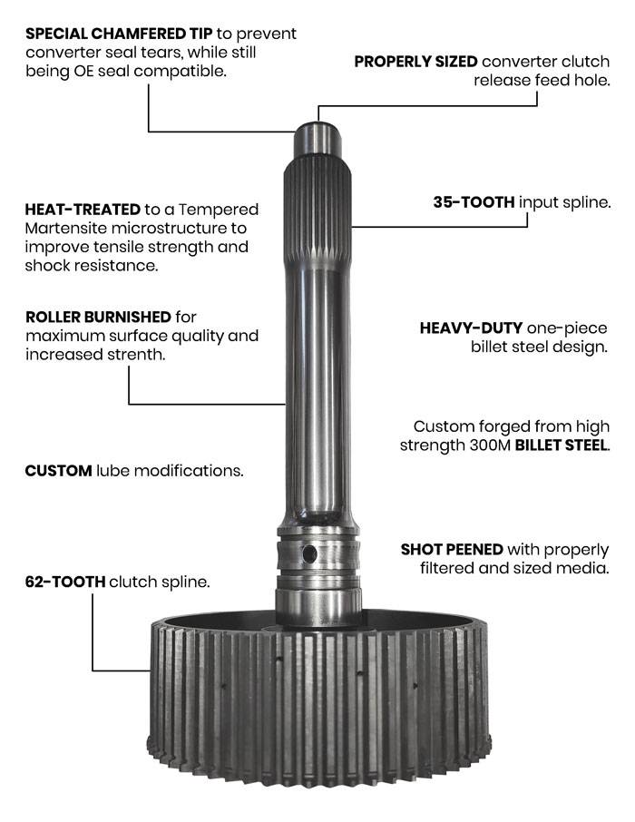
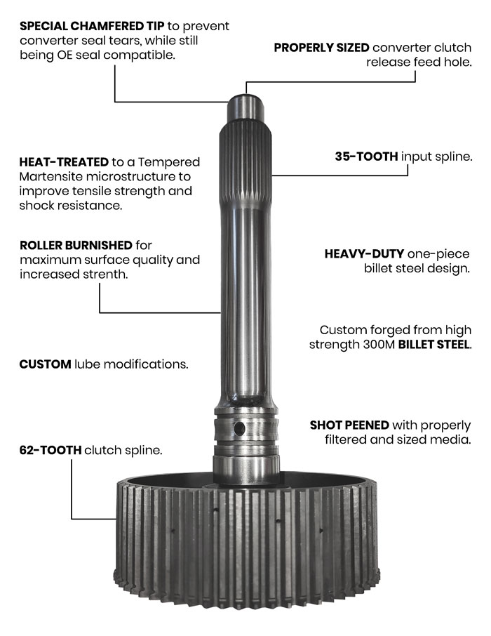
Our heavy duty 35-spline billet input shaft is custom forged from High Strength 300M steel and incorporates a 35-tooth input spline and 62-tooth clutch spline. This shaft utilizes a heavy duty one-piece design, and comes with Goerend lube modifications. The billet apply piston includes clearance for the taller clutch hub splines of the input shaft. This shaft does not fit non-lock transmissions.
What's in the box?
- (1) 35-spline heavy-duty input shaft
- (1) 35-spline stator support assembly
- (2) Turbine shaft Teflon sealing ring, butt-cut
- (1) Apply piston, front (direct) clutch
Chemical Analysis:
% By Weight:
- 93.45 - Iron
- 1.99 - Nickel (ICP-OES)
- 1.70 - Silicon (ASTM E1024)
- 0.88 - Manganese (ICP-OES)
- 0.86 - Chromium (ICP-OES)
- 0.43 - Carbon (ASTM E415)
- 0.42 - Molybdenum (ICP-OES)
- 0.14 - Copper (ASTM E415)
- 0.08 - Vanadium (ASTM E415)
- 0.012 - Aluminum (ASTM E415)
- 0.011 - Phosphorus (ASTM E415)
- 0.010 - Lead (ASTM E415)
- <0.001 - Sulfer (ASTM E415)
- <0.001 - Titanium (ASTM E415)
- <0.001 - Niobium (ASTM E415)
Rockwell Hardness Test:
Scale: HRC
Method: ASTM E18
- Location 1 - 52.4
- Location 2 - 52.0
- Location 3 - 53.0
- Location 4 - 52.8
- Location 5 - 52.8
- Location 6 - 53.2
- Location 7 - 54.2
FAQ
Can I use an OEM apply piston with this shaft?
No, an OEM apply piston will hit the splines of the input shaft.
Can I use a TCS apply piston with this shaft?
The apply pistons included with K123900S and K123900SH are compatible with this shaft.
What is the horsepower rating for this shaft?
We don't rate our shafts for horsepower. This is because a shaft can break for multiple reasons, regardless of a vehicles horsepower, such as shock loads, bindups, and fatigue.
Why do transmission shafts break?
Transmission shafts can break for different reasons. One thing that will affect shafts is fatigue. If you bend a wire hanger back and forth enough times, the wire will fatigue and eventually break. This fatigue will happen with shaft use over time as well.
Shock loads tend to break input shafts, since they are usually the weakest shaft in the transmission.
One example of a shock load is in Baha racing, where the vehicle may leave the road surface and jump into the air. If the driver is still holding the throttle with the vehicle suspended in air, the vehicle's wheels will spin up faster due to the lack of resistance between the tires and the ground. When coming back in contact with the ground, there will be a shock load.
Another example will be when a vehicle is stuck and one of its wheels is freely spinning. If the freely spinning wheel is able to suddenly get full traction, it will create a shock load. Shock loads can tend to break at the stress risers of shafts, such as at the side lubrication holes of input shafts and at the front set of splines during a 1-2 shift on intermediate shafts.
Sometimes there is an opposite shock load. Examples of this can be found in semis. When a semi drives over a small bump in the road, its wheels may leave the road surface for an instant. When off the road, this allows the semi's trailer wheels to slow down. When these wheels do contact the road again, they will instantly need to speed up to match the speed of the vehicle. This will create a shock load, and will also leave a black mark on the road.
Bind up shifts happen when two gears are engaged at the same time for a fraction of a second. Bind up shifts will try to twist the shaft. Bind up shifts can also cause shock loads.
Transmission Shaft Overloading
During a boosted launch, when holding both the brakes and a full throttle, the intermediate and output shafts can become overloaded and can break in either a ductile or brittle manner. A ductile manner would mean that the shaft twisted before breaking. A brittle manner would mean that the shaft broke before twisting occurred. The intermediate shaft can break at the center or rear spline when overloaded.
How does stator support alignment affect converter lockup?
Converter lockup issues are often traced back to obvious problems such as worn clutches, but small changes inside the pump assembly can have a direct impact on oil flow, and ultimately whether the converter clutch ever applies.
One key component in this system is the stator support. Its position within the transmission isn’t just structural. It directly affects the alignment between sealing surfaces and the oil feed passages that supply the converter. When everything is in its correct location, fluid routes cleanly through the input shaft seals and into the converter, allowing the clutch to apply as intended.
If the stator support is machined or otherwise repositioned, even slightly, it can shift the relationship between the seals and the oil feed holes. This doesn’t necessarily show up as a hard failure during assembly. In many cases, the only immediate sign is the need to adjust thrust clearances, often by installing thicker washers to bring everything back into spec. While that may restore endplay, it doesn’t correct the underlying alignment issue.
The result can be a misalignment where the sealing surfaces no longer properly register with the oil passages. When that happens, converter feed oil can be restricted or blocked entirely. Without sufficient oil flow, the converter clutch won’t receive the hydraulic pressure it needs to engage, leading to a no-lockup condition even though the rest of the system appears functional.
If clearances are significantly off from what would be considered normal, it’s worth verifying that all components, especially the stator support, are dimensionally correct and properly positioned. Using thicker washers to compensate may hide a deeper issue rather than solve it.
As power levels increase and transmission builds become more demanding, the margin for error shrinks. Proper oil circuit alignment becomes even more critical, and small deviations in component alignment can have outsized effects. Maintaining correct dimensions and verifying seal-to-passage alignment during assembly are essential steps in ensuring consistent converter lockup and overall transmission performance.
Details
- D121-104-G35SK
- D121-104-G35SK
- Goerend
- New
Categories
Shipping Information
- Item Requires Shipping
- 16.0 lbs.
- W10.0000” x H14.0000” x L12.0000”