- Home »
- FAQ
Goerend Transmission FAQ
- Privacy Policy
- Shipping & Returns
- FAQ
- Does Goerend still build full transmissions?
- Diagnosing Limp Mode on a 1996 Dodge 12-Valve Cummins
- How does a torque converter work?
- What determines stall speed?
- How Torque Converters Shape Power Delivery in Performance Builds
- What is true, flash, and breakaway stall speed?
- Lock Up & Speed Ratio
- Torque Converter Clutch Drag Caused by a Stuck Pressure Regulator Valve
- Why do torque converter clutches warp?
- How do I know if I have a Goerend converter?
- Should I use a threadlocker on my torque converter bolts?
- Diagnosing Heat-Related Lock-Up Issues
- Torque Converter Rebuild Procedure
- Why is my torque converter overheated?
- Non-VGT Turbo Spool-Up and Boost Behavior
- Why do transmission shafts break?
- Transmission Shaft Overloading
- Transmission Shaft Materials
- How does stator support alignment affect converter lockup?
- What transmission filter should I use?
- What transmission fluid should I use?
- My transmission fluid looks like a strawberry milkshake?
- Do I need Lubeguard additive?
- Normal Transmission Temperatures & Sender Locations
- What's the 48RE transmission pan temperature sender port size?
- Should I use an RTV silicone sealant with my transmission pan?
- Chrysler 47RH, 47RE, and 48RE Transmission Fluid Capacity Instructions
- Dodge 1740 Code
- How do I adjust the low/reverse (rear) band?
- How do I adjust the intermediate (front) band?
- Will a new valve body cure my shifting problems?
- Neutralizing Conditions
- Towing, Sled Pulling & Drag Racing Valve Bodies
- What's a constant-pressure valve body?
- Is there a valve body that works for daily driving, towing, drag racing, and sled pulling?
- Where does the big spring go that comes with a new valve body?
- What does the throttle valve lever do?
- Do all valve bodies need the extra inner front servo piston return spring?
- Understanding a 48RE 3–4 upshift flare
- Should I use the OEM shim with the Goerend Allison 1000 flexplate?
- Flex Plate Engineering: Balancing Strength & Flexibility
Privacy Policy
Q: Intellectual Property
Goerend owns the registered trademark “GOEREND” for automotive automatic transmissions; automotive transmission replacement parts, namely, transmission pans, flex plates, valve bodies and billet shafts, transmission rebuild kits sold as a unit, turbines; and torque converters for land vehicles. Goerend has used the trademark on a regular and consistent basis in commerce since January 1990. United States Trademark Registration No. 6093647.
Goerend owns the registered trademark “POWER TO THE GROUND” for automotive automatic transmissions; automotive transmission replacement parts, namely, transmission pans, flex plates, valve bodies and billet shafts, transmission rebuild kits sold as a unit, turbines; and torque converters for land vehicles. Goerend has used the trademark on a regular and consistent basis in commerce since February 2014. United States Trademark Registration No. 6066818.
Goerend does not permit any other person or business entity to use any trademark owned by Goerend, unless specifically referring to products manufactured by Goerend, or Goerend Transmission, Inc., the company itself.
- Any use of Goerend trademarks must be accompanied by the ® symbol, indicating that the mark is a registered trademark of Goerend Transmission, Inc.
- The trademarks may not be used in any way that suggests an endorsement or sponsorship by Goerend of a third party’s products or services.
- The trademarks may not be used in any way that is likely to cause confusion among customers as to the source of the goods being offered.
- The trademarks may not be used in any way that is derogatory, defamatory, or harmful to the reputation of Goerend or its products.
- The trademarks may not be used in any way that is misleading or deceptive.
- You may not link to any pictures on our website, nor directly copy any descriptions without our written consent.
- You may not use or copy our intellectual property (including our logos, trademarks, and copyrighted material) without our written consent.
- Any use of our intellectual property without our written consent is a violation of federal law and may lead to prosecution.
If you have any questions regarding our intellectual property policies or if you would like to report a situation which you believe should be brought to our attention, please contact us at goerendmason@gmail.com.
We take infringement seriously, monitoring and diligently protecting our intellectual property. Any unlicensed use of any of our trademarks is a violation of our exclusive rights and may cause confusion among customers as to the source of the goods being offered. We urge all third parties to comply with our guidelines and respect our intellectual property rights.
Q: Communications to Serve You
Q: Disclosure of Personally Identifiable Information
Q: Fraud Protection and Compliance with Law
Q: Service Providers
Q: Cookies, IP Addresses, Pixel Tags and Tracking Technology
Q: Use of Aggregate Information
Q: Links
Q: Notification of Policy Changes
Q: Contacting Us
Shipping & Returns
Q: SHIPPING OPTIONS
Q: SHIPPING COST
Q: SHIPPING TIMES
Q: INTERNATIONAL CUSTOMERS
International orders may be subject to additional international fees after purchase. Customer is responsible for all international fees, customs, duties, taxes, or other associated costs. We may charge customer's original payment method anytime after sale relating to any additional charges billed directly to Goerend on applicable orders.
Q: EDITING ORDERS
Q: RETURNS
FAQ
Q: Does Goerend still build full transmissions?
Q: Diagnosing Limp Mode on a 1996 Dodge 12-Valve Cummins
In this case, the truck had been sitting for a while and the batteries went dead. After recharging the batteries, the transmission suddenly began starting in a high gear with no overdrive or lockup. The owner noticed right away that the truck felt like it was taking off in third gear. Pulling the shifter manually into low helped get the truck moving, but shifting into second often did nothing, and shifting into drive only produced one upshift.
Those are classic signs that the transmission has lost 12-volt power to the solenoid circuit.
On a 47RE and 48RE transmission, losing power to pin number one at the eight-pin connector on the driver side of the transmission forces the unit into fail-safe operation. The transmission defaults into third gear and disables overdrive and converter lockup.
The first place to check is the fuse and relay box behind the driver-side battery. A 10-amp fuse feeds the transmission relay. If that fuse blows or develops a poor connection, the transmission loses power. Even if the fuse looks good, corrosion or age can still cause problems.
If the fuse checks out, the next step is swapping the transmission relay with another identical relay in the box, such as the horn relay. If the transmission starts working normally afterward, the relay was the problem.
Another quick test is jumping the two large terminals in the relay socket. One terminal supplies battery power while the other sends power to the transmission. Jumping them together bypasses the relay completely. If the truck immediately regains first gear starts, overdrive, and lockup, the issue is likely in the relay control circuit, ECM, or wiring.
Many owners permanently run this jumper setup when installing manual lockup switches, so leaving it installed generally causes no issues.
The transmission shop in this case claimed the unit was “full of iron” and needed replacement, but the owner described only a gray fuzzy coating on the magnet with no chunks or gritty debris. That is completely normal. Automatic transmissions naturally produce fine metallic dust during normal wear, which is exactly why the pan contains a magnet in the first place.
The important detail was that the transmission had never slipped and had worked fine before the batteries went dead. That strongly pointed toward an electrical problem instead of internal transmission failure.
Before spending thousands of dollars rebuilding a Chrysler 47RE or 48RE transmission, always verify power to the transmission first. A blown fuse, weak relay, bad connection, or missing 12-volt feed can create symptoms that look severe while the transmission itself is still perfectly healthy.
Q: How does a torque converter work?
Let’s start with two wall fans facing each other. If we turn one fan on, the air from this fan will start to turn the other fan, although at a much slower rate than the "drive" fan.
In the case of a torque converter, the drive fan is connected to the engine, and the fan being “driven” is connected to the input shaft of the transmission. In addition, oil is used to transmit the energy between the two fans, as opposed to air in the example scenario.
When a vehicle is stationary, such as at a stop sign, with the transmission in gear and engine at idle, the drive fan that is connected to the engine is spinning so slow that it will not transfer enough oil to turn the driven fan. As the vehicle’s brakes are let off and the throttle is held, the engine speed increases, and the drive fan blows more oil at the driven fan. The driven fan then starts to turn and move the vehicle. This important concept is commonly referred to as fluid coupling.
The drive fan will always turn slightly faster than the driven fan, just like the wall fans. If you were to stick a feather into the blades of the driven wall fan, the driven fan will slow down, but not the drive fan. In a real application, this is just like pulling a heavier trailer. The feather in the driven wall fan is essentially like adding a load to the vehicle.
Q: What determines stall speed?
The two major things that determine the stall speed are engine torque and the torque converter.
This is one way to think about it: You’re on a stationary exercise bike that uses a fan for its pedal resistance. The smaller the fan is, the faster you can pedal. You may be able to pedal up to 200 RPM on the bike with a small fan, but only be able to pedal up to 50 RPM if you fit a bigger fan on the bike. The small fan was able to stall you at 200 RPM and the bigger fan stalled you at 50 RPM. Two different fans, two different stall speeds.
Now a professional athlete hops on the bike. With the big fan, they may be able to pedal 100 RPM, as opposed to your 50 RPM.
To compare this to the engine torque and torque converter, you must remember that a torque converter is nothing more than two fans. One fan is connected to the engine and the other fan is connected to the transmission. The fan connected to the engine blows oil at the fan connected to the transmission. Once the engine fan blows enough oil at the transmission fan, the transmission fan will start to rotate. The vehicle will then start to move.
Just like the exercise bike analogy, if you install a torque converter with bigger fan blades into a vehicle with the same engine torque, the stall speed will be lower. If you add more horsepower to the engine, just like the athlete hopping on the exercise bike, the stall speed will increase.
Now let’s talk about air. It's all about the oxygen. You’ll be able to pedal harder on the bike at sea level than on the top of a mountain because you’ll be able to breathe better, since there is more oxygen in the air. Similar to your lungs, an engine is nothing more than an air pump that uses fuel. The fuel an engine uses must react with oxygen in order to push the piston down and turn the crankshaft.
The higher the elevation, the less oxygen the engine has to work with, and the less fuel that can be injected to react with the oxygen. By using less fuel, it means the power input into the converter will be lower, resulting in a lower stall speed. Normally, the higher the elevation, the higher the stall speed that is needed in order to help offset the lack of oxygen that is present at sea level.
The engine turbo also can make a huge difference. Like the converter, the turbo is also a set of fans. The drive fan is located in the exhaust of the engine and it’s the exhaust flow makes this fan spin.
The driven fan of the turbo is connected to the drive fan and sits on the intake side of the engine. The driven forces oxygen into the engine so it can burn more fuel, resulting in more power.
A turbo with bigger fans takes longer to spool up and start to blow more air into the engine. Because of this, it takes longer to get oxygen into the engine cylinders to burn fuel. This is called turbo lag.
Q: How Torque Converters Shape Power Delivery in Performance Builds
A useful way to understand this is by looking at how a converter behaves across different operating conditions rather than at a single fixed point. Engine torque, vehicle load, and speed all interact to determine how quickly the engine can rev and how effectively that energy is transferred through the drivetrain.
At low vehicle speeds, such as when accelerating from a stop, the converter allows a certain amount of slip between the engine and the transmission. This slip is what enables the engine to build RPM before the vehicle fully responds. A converter that allows more slip in this range will let the engine rev higher under load. This is often described as being “looser,” but more broadly, it reflects how aggressively the drivetrain allows the engine to get into its powerband early.
As speed increases, however, efficient power transfer becomes more important than initial responsiveness. Ideally, a converter transitions from allowing slip to tightening up, reducing the difference between engine speed and transmission speed. This improves efficiency, reduces heat, and ensures that more of the engine’s power is actually driving the vehicle forward rather than being lost in the fluid coupling.
What makes certain converter designs effective is their ability to balance these two behaviors. A well-matched setup will allow the engine to build RPM quickly at low speeds, helping with acceleration and, in turbocharged applications, improving spool while still coupling efficiently as speed rises.
Engine torque also plays a critical role in this behavior. Higher torque levels tend to drive the converter harder, changing how quickly it moves through its operating range. This is why the same converter can behave differently depending on the power level of the setup. Rather than thinking of a converter as having a single fixed stall speed, it is more accurate to view it as a dynamic component that responds to the load placed on it.
In practical terms, this means that selecting the right converter is less about chasing a specific number and more about matching its behavior to the goals of the build. Setups that prioritize quick response and strong low-speed acceleration benefit from designs that allow the engine to rev more freely under load. Applications focused on sustained power delivery and efficiency may favor tighter coupling characteristics.
Ultimately, the goal is to create a system where the engine and transmission work together seamlessly. The converter acts as the bridge between them, shaping how power is introduced, managed, and sustained across the entire driving range.
Q: What is true, flash, and breakaway stall speed?
To explain stall speed, let’s start with a true full stall speed.
True stall speed is tested by putting the vehicle in drive and holding the throttle wide open while simultaneously holding the brake, so the vehicle remains stationary. When this happens, the torque converter will stall the engine at a certain RPM. When stalled, the engine will not be able to increase RPM until the vehicle is allowed to move. This is a true full stall. Do not test for true stall, as it can damage transmission shafts and overheat the torque converter. We have specialized equipment we use to perform this test.
The next stall speed is generally known as breakaway stall speed. A vehicle in drive is stopped on an incline and the throttle was held enough to hold the vehicle in place, but not enough to move the vehicle uphill. Once the throttle is held enough to start creeping the vehicle uphill, breakaway stall speed has been reached. For example, if the engine RPM required to hold the truck is 1100 RPM, and an increase of 25 RPM started to move the truck, the breakaway stall speed would be 1125 RPM.
The last stall speed is generally known as flash stall speed. The flash stall speed takes effect under hard acceleration. A vehicle idling in drive and the throttle is then held wide open. The engine starts to accelerate quickly, then temporarily pause at an RPM as it starts to pull the vehicle. If the engine took 1.5 seconds to get from an idle to 1500 RPM when floored, then took another two seconds to get from 1500 RPM to 2000 RPM, this would mean the flash stall speed would be 1500 RPM.
When we lower the stall of a converter, it can also lower the breakaway stall speed as well as the flash stall speed. Lowering the stall makes the engine work at a lower RPM for any given road speed and in most cases, will increase fuel mileage.
Q: Lock Up & Speed Ratio
Once a vehicle gets up to speed there is a mechanism called a lock up clutch that locks the driven fan of the torque converter to its front cover, which is bolted to the engine. When this occurs, the drive fan and driven fan turn at the same RPM, with no loss of power in fluid coupling.
When the drive and driven fan are not locked together, heat is generated inside the converter. The greater the RPM difference between the drive and driven fan, the higher the temperature will reach. This heat is essentially lost power which results in a lower transmission life, performance, and fuel economy.
The loss of energy in this process can be calculated. A converter’s drive fan (impeller) may be turning at 2500 RPM and the driven fan (turbine) may be turning at 1800 RPM. By dividing the turbine RPM by the impeller RPM, we can find the efficiency of the converter, which is 72% at the given speeds of the impeller and turbine. This efficiency rate is also known as a converter’s speed ratio. When the vehicle gets up to speed and the lock up clutch engages, the engine and impeller RPM match the RPM of the turbine.
Low stall converters will be able to achieve a higher speed ratio before lock up. When low stall converters lock up, their RPM drop is substantially less, therefore easier on the converter’s clutch lining and will reduce clutch glazing. Because the fluid coupling of a low stall converter is more efficient, they are able to transfer more power, create less heat, and deliver better fuel economy than high stall converters.
Q: Torque Converter Clutch Drag Caused by a Stuck Pressure Regulator Valve
The converter passed lockup testing and showed no signs of mechanical failure. However, inspection of the valve body revealed metallic debris throughout the fluid along with contamination on the outside of the valve body. The pressure regulator valve was also found stuck in an open position.
Tracing the hydraulic circuits showed the stuck valve created a direct exhaust path for both line pressure and converter charge oil. With converter release oil exhausting internally, the converter clutch could not fully disengage at idle.
Although the converter contains a front cover bushing, that bushing is not known as a common failure point. This shifted suspicion toward internal transmission bushings, thrust washer damage, or contamination circulating through the cooler system.
The pressure regulator valve controls line pressure by balancing pump pressure against spring tension and hydraulic feedback oil. Under normal operation, the valve constantly moves in small increments to regulate excess pressure while maintaining converter charge oil and converter clutch release pressure.
Hydraulic feedback oil is routed through passages in the separator plate and channel casting to the backside of the valve, allowing the valve to continuously balance pressure demand and exhaust flow. The valve should never remain fixed in a fully open position.
In this case, debris contamination prevented the valve from returning to its closed position. With the valve stuck open, both line pressure and converter release pressure were continuously exhausted.
At higher RPM, increased pump volume partially compensated for the leakage. At idle, however, converter release pressure dropped low enough that the clutch could not fully separate. The converter clutch remained applied or partially applied, causing the engine to stall when the vehicle came to a stop.
Despite the drivability complaint, the converter still functioned normally on the lockup tester.
Although converter clutch drag may have created additional heat and wear inside the converter, that alone would not explain the metallic debris discovered on the valve body. This reinforced the need to locate the original contamination source.
The amount of debris found on the valve body indicated material was being generated somewhere within the transmission system. Possible sources included internal transmission bushings, thrust washers, pump components, or contamination trapped within the cooler system.
The transmission required complete inspection for damaged bushings and thrust washers, including the pump assembly, stator support, planetary assemblies, and rotating hard parts.
The converter was cut open for inspection, but the converter bushing was verified as acceptable. The final repair recommendation after inspection of the converter and valve body, was inspecting all transmission bushings and thrust washers, and carefully checking the pump assembly for wear or damage.
If no internal transmission damage could be identified, the cooler system became the next likely source of contamination. Coolers can trap metallic debris and recirculate contamination into rebuilt units, especially after previous failures. In situations where contamination cannot be completely eliminated, replacing the cooler is often safer than attempting to flush it.
This case highlights an important diagnostic principle in transmission repair. A vehicle stalling at stop signs due to a locked converter clutch does not automatically indicate a failed converter. Hydraulic regulation problems, valve sticking, contamination, pressure loss, low fluid level, or a displaced filter can all create the same symptom.
It also demonstrates how a single stuck pressure regulator valve can mimic major component failure by exhausting converter release oil and preventing the clutch from disengaging properly.
Most importantly, any time metallic debris is found inside a transmission, the source must be identified. Replacing components without locating the origin of contamination often results in repeat failures.
This case highlights the importance of diagnosing converter clutch release hydraulics before condemning major transmission components.
Q: Why do torque converter clutches warp?
Inside a lockup torque converter, hydraulic pressure is used to release and apply the converter clutch. During normal unlocked operation, oil pressure fills the release circuit and pushes the clutch piston away from the front cover, creating the clearance necessary for the converter to operate hydraulically. When lockup is commanded, the oil flow is reversed, applying the piston firmly against the cover to create a mechanical connection between the engine and transmission.
Problems occur when there is not enough release oil flow or pressure to keep the clutch separated. Even though the converter is commanded to be unlocked, the clutch can lightly drag against the front cover. This constant contact generates heat, and on traditional triple-disc converters, the single-sided steel floater plate is especially vulnerable. Because friction material insulates one side of the plate while the opposite side is exposed directly to the heat generated by dragging, the plate heats unevenly and begins to warp.
Another situation that can produce clutch drag is prolonged high engine speed while the converter remains unlocked. Centrifugal force acting on the oil inside the converter can momentarily push the piston toward the front cover. As the piston moves, it restricts the release oil supply, causing the clutch to repeatedly contact and separate from the cover. This cycling creates additional heat and accelerates clutch distortion.
Insufficient release oil can result from several hydraulic issues, including excessive line pressure, worn pressure regulator valve bores, restricted converter feed circuits, or transmission calibrations that increase line pressure without providing additional converter lubrication. Increasing line pressure alone does not necessarily improve durability. If converter feed and lubrication circuits are not increased proportionally, the converter may receive less release oil, causing clutch drag while also reducing cooler flow and increasing transmission operating temperatures.
Warped converter clutches often produce symptoms such as shuddering, harsh engagement, abnormal converter noise, or metal contamination in the transmission. In many cases, the transmission itself may show little or no internal damage. However, the transmission cooler and cooler lines should always be thoroughly cleaned or replaced whenever converter debris is present to prevent contamination of replacement components.
For applications that experience severe use, upgrading to a converter with double-sided clutch linings and a heavier floater plate can improve resistance to heat-induced warping. While this design does not increase torque capacity by itself, it distributes heat more evenly across the clutch assembly and greatly reduces the likelihood of plate distortion during demanding operating conditions.
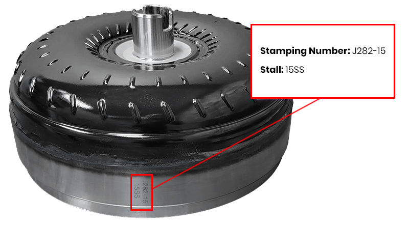
Q: How do I know if I have a Goerend converter?
If your converter originated from Goerend, there will be a series of numbers stamped into the outside cover. To find this series of numbers follow these steps:
- Remove inspection plate
- Rotate converter until you see the stamping number
Q: Should I use a threadlocker on my torque converter bolts?
While you don't need to use a threadlocker, such as Loctite, on your torque converter bolts, we would recommend using Loctite Blue if you choose to use a threadlocker.
Q: Diagnosing Heat-Related Lock-Up Issues
Lock-up complaints are often blamed on the torque converter, but real-world diagnostics don’t always point that cleanly in one direction.
The issue presents as a temperature-dependent lock-up problem. When cold, the converter clutch applies and holds reasonably well. As operating temperature increases around 115°F, lock-up performance begins to degrade. Under light load, the clutch can still be felt engaging, but it lacks holding strength. Under throttle, it slips entirely, with engine RPM rising independently of vehicle speed.
At face value, this looks like a failing converter clutch. However, testing tells a more complicated story. The converter was checked on a lock-up test fixture using applied air pressure and measured torque resistance. Even at relatively low test pressure, it demonstrated strong holding capacity, well within what would be expected for the application. This suggests the converter is capable of holding torque, at least under static conditions.
That creates a gap between bench results and real-world behavior. When a converter passes static testing but the transmission slips under load, it points to a system-level issue rather than an immediate component failure. Heat changes fluid viscosity, internal clearances, and sealing effectiveness. Any weakness in the apply circuit, whether inside the converter or elsewhere in the transmission, may only appear under these conditions.
In cases like this, it becomes important not to jump straight to condemning the converter. The correct next step is verification: either testing under load (dyno) or physically inspecting the converter internals. This kind of problem underscores a broader principle in transmission diagnostics: lock-up slip under heat doesn’t automatically mean the converter is bad. It often indicates that something in the transmission system such as pressure supply, sealing, or internal leakage.
The takeaway is simple. If a failure only occurs hot and under load, you’re no longer just diagnosing a part, you’re diagnosing the entire transmission system.
Q: Torque Converter Rebuild Procedure
- All parts and internal components are cleaned and inspected
- Impeller, turbine, stator, clutch plates, damper assemblies, and covers are all balanced individually
- Torque converter is assembled and multiple internal and external dimensional inspections are completed
- Torque converter is welded together by TCRS alignment equipment with sub-0.003 runout tolerances
- Torque converter is leak-tested under water, while under pressure
- Torque converter is balanced as a unit and the runout tolerance is inspected again
- Total height of the torque converter is inspected
- Internal end-play is inspected
- Lock up clutch is applied and inspected for leaks and holding power
- Lock up clutch is released; the lock up clutch and turbine are spun while the impeller is stationary
- Lock up clutch is examined to insure proper release and no interference between internal components
- Impeller hub is lubricated and a protector cap is placed
- New bolts are provided where necessary
Q: Why is my torque converter overheated?
Q: Non-VGT Turbo Spool-Up and Boost Behavior
Q: Why do transmission shafts break?
Q: Transmission Shaft Overloading
Q: Transmission Shaft Materials
Q: How does stator support alignment affect converter lockup?
One key component in this system, especially a Chrysler 48RE, is the stator support. Its position within the transmission isn’t just structural. It directly affects the alignment between sealing surfaces and the oil feed passages that supply the converter. When everything is in its correct location, fluid routes cleanly through the input shaft seals and into the converter, allowing the clutch to apply as intended.
If the stator support is machined or otherwise repositioned, even slightly, it can shift the relationship between the seals and the oil feed holes. This doesn’t necessarily show up as a hard failure during assembly. In many cases, the only immediate sign is the need to adjust thrust clearances, often by installing thicker washers to bring everything back into spec. While that may restore endplay, it doesn’t correct the underlying alignment issue.
The result can be a misalignment where the sealing surfaces no longer properly register with the oil passages. When that happens, converter feed oil can be restricted or blocked entirely. Without sufficient oil flow, the converter clutch won’t receive the hydraulic pressure it needs to engage, leading to a no-lockup condition even though the rest of the system appears functional.
If clearances are significantly off from what would be considered normal, it’s worth verifying that all components, especially the stator support, are dimensionally correct and properly positioned. Using thicker washers to compensate may hide a deeper issue rather than solve it.
As power levels increase and transmission builds become more demanding, the margin for error shrinks. Proper oil circuit alignment becomes even more critical, and small deviations in component alignment can have outsized effects. Maintaining correct dimensions and verifying seal-to-passage alignment during assembly are essential steps in ensuring consistent converter lockup and overall transmission performance.
Q: What transmission filter should I use?
For best results, use Mopar transmission filters.
We prefer to use the early style open element filter because it will seal up better. The exception to this would be the deep factory stamped pan. This pan should take the late style plastic filter because it will sit deeper in the fluid within the pan.
Q: What transmission fluid should I use?
Chrysler 47RH, 47RE, and 48RE transmissions have used Dexron fluid, Chrysler 7176 fluid, Mopar type 3 fluid, and now Mopar type 4 fluid. We have used all of these fluids without any problems. There are many fluids you can use, and most synthetics are fine to use as well.
Q: My transmission fluid looks like a strawberry milkshake?
Q: Do I need Lubeguard additive?
Lubeguard will help keep the transmission cooler, and is supposed to help clutches last longer. It's not a necessity, but those would be the potential benefits if you choose to use it. You can purchase Lubeguard additive at a NAPA store. Part #: BK 7652966. This is transmission fluid additive, not additive for the gas tank.
Q: Normal Transmission Temperatures & Sender Locations
Q: What's the 48RE transmission pan temperature sender port size?
Q: Should I use an RTV silicone sealant with my transmission pan?
Q: Chrysler 47RH, 47RE, and 48RE Transmission Fluid Capacity Instructions
OE Pan: Holds approximately 14 qts.
- Pour in 6 quarts of transmission fluid into dipstick tube.
- Start vehicle.
- Add 7 - 8 more quarts of transmission fluid into dipstick tube.
- Check fluid level. The transmission must be in neutral because the factory valve body on these transmissions will not fill the converter in park.
- Look at both sides of the dipstick and take the reading from the low side.
- Add transmission fluid until full.
- Recheck fluid level after driving 5 - 10 miles.
Goerend Pan: Holds approximately 16 qts.
- Pour in 8 quarts of transmission fluid into dipstick tube.
- Start vehicle.
- Add 6 - 8 more quarts of transmission fluid into dipstick tube.
- Check fluid level.
- The transmission must be in neutral because the factory valve body on these transmissions will not fill the converter in park.
- Look at both sides of the dipstick and take the reading from the low side.
- Add transmission fluid until full.
- Recheck fluid level after driving 5 - 10 miles.
Double Deep Pan: Holds approximately 19 qts.
- Pour in 8 quarts of transmission fluid into dipstick tube.
- Start vehicle.
- Add 9 - 11 more quarts of transmission fluid into dipstick tube.
- Check fluid level. The transmission must be in neutral because the factory valve body on these transmissions will not fill the converter in park.
- Look at both sides of the dipstick and take the reading from the low side.
- Add transmission fluid until full.
- Recheck fluid level after driving 5 - 10 miles.
Q: Dodge 1740 Code
On a late model truck, usually 2004 - 2007, any stall speed different than the factory stall (17SS or DA) can set a 1740 code. This code will turn on the check engine light but will not affect the operation of the transmission or engine. This code sets because the computer constantly monitors the engine RPM and compares it to the throttle angle and road speed.
With a lower stall converter, the computer sees the lower engine RPM and thinks the lock up or overdrive solenoid is mechanically stuck on. The computer can check for electrical faults and will not detect any, and thinks the lower RPM is due to the converter being locked up or the transmission is in overdrive, even though it's not. Most programmers can erase the 1740 code. This code will not affect the transmission or engine operation if both are working normally otherwise.
Q: How do I adjust the low/reverse (rear) band?
Tighten the adjuster to 72 inch-pounds and loosen 3¼ full turns.
Q: How do I adjust the intermediate (front) band?
If a vehicle is equipped with a Goerend valve body, loosen the lock nut and tighten the adjustment bolt to 72 inch-pounds and finally loosen 2¼ turns.
Q: Will a new valve body cure my shifting problems?
Many shifting problems can be cured by a valve body, but the shift timing is controlled by the computer. On a Chrysler 47RH and older transmissions, the 3-4 and converter lock up is computer controlled. On a Chrysler 47RE and newer transmissions, all shifts will be controlled by the computer. This means that a bad input to the computer, such as a bad throttle position sensor or output shaft speed sensor, can affect the shifting. This would then seem like a valve body problem, even though it is not.
Q: Neutralizing Conditions
Some vehicles have problems while accelerating at about 3/4 throttle around 40 MPH, when trying to shift from 2nd to 3rd gear. The transmission will neutralize and the engine revs up, just like it shifted to neutral instead of 3rd gear. If the throttle is then let off, it bangs into 3rd gear.
A Goerend valve body will correct this, as long as the governor solenoid is in good condition.
Many valve body builders do not know that the torque converter circuit is regulated to 130 PSI from factory, so it is common practice to eliminate this circuit and give the converter full line pressure. This practice is the main cause of ballooned converters. A Goerend valve body will have the proper regulation in the converter circuit.
Q: Towing, Sled Pulling & Drag Racing Valve Bodies
We want a smooth shift on a towing valve body. This helps keep shafts and planetary gears from breaking due to the shock of brutal shifts. We also build the valve body so you can downshift from 4th to 3rd and from 3rd to 2nd with the converter locked in case you have an exhaust brake. If a toggle switch is installed, you can also lock the converter while in manual 2nd so the converter will not overheat while towing a heavy load up a steep grade.
With a sled pulling valve body, You'll be capable of locking the converter clutch in 1st, 2nd, 3rd, and overdrive and also be able to back shift from overdrive to 3rd, 2nd, and 1st with the converter locked.
On a drag racing valve body, we normally lock the converter right after the 1-2 shift. We're able to build the valve body so it will not lock the converter in 1st. In doing so, you'll be able to turn the lock up switch on while at the starting line without killing the engine, and as soon as it shifts to 2nd, the converter will automatically lock up.
Q: What's a constant-pressure valve body?
Normally, the pressure that applies the clutches and bands in a transmission will be low at idle and high at full throttle. With a constant-pressure valve body, the pressure is high at all times, both at idle and wide open throttle. Constant-pressure valve bodies are only recommended for high-horsepower and racing applications. Constant-pressure valve bodies shift aggressively and can cause fatigue to internal transmission components over time.
Q: Is there a valve body that works for daily driving, towing, drag racing, and sled pulling?
Yes and no. Up to about 500 horsepower, the same valve body can work well for all. Once above 500 horsepower, there are things needed to be modified on the valve body that would be specific to drag racing and sled pulling that would not be made to a daily driver or tow rig valve body.
Q: Where does the big spring go that comes with a new valve body?
This spring goes into the intermediate (front) band apply servo along with the original spring. This is the servo that applies the front band.
Q: What does the throttle valve lever do?
The TV lever basically does three things:
1: It makes the transmission line pressure increase when you increase the throttle. When you step into the throttle for more power the line pressure goes up so the clutches and bands don't slip.
2: It will delay the shifts with increased throttle. You wouldn’t want the transmission to be in high gear at 40 MPH at wide open throttle, but you would want the transmission to be in high gear at light throttle.
3: At light throttle, the TV lever, along with governor pressure and the 1-2 shift control valve, dictate how fast the front band is released. The band is released quickly at light throttle so there is no bind up. The front band is released slower at wide open throttle so there is no cut loose or engine flare.
With a ranging-pressure manual valve body, you would have the TV lever adjusted just like a normal valve body for smooth shifts at light throttle, and quicker shifts at full throttle.
With a constant-pressure manual valve body, the only thing the TV lever will do is release the front band sooner at light throttle, or slower at heavy throttle. We would use an old choke cable, such as an old carburetor, and connect it to the TV lever. At light throttle, the lever would be all the way forward for a smoother 2-3 shift. At full throttle, you would pull the choke cable so the lever is all the way back so there was not a flare during the shift.
Q: Do all valve bodies need the extra inner front servo piston return spring?
This is a calibration spring for the 2-3 shift. We use this spring as the calibration spring because the other calibration points are inside the transmission, meaning we would have to remove the entire transmission to calibrate the shift.
Normally, we would start with this spring installed. If there was a cutloose or engine flare during the 2-3 shift, we could remove this spring to eliminate the cutloose. The opposite of the cutloose is a bind up shift. This can break an input shaft, even if it is billet steel. It's better to start with this spring installed and remove it later, than to start without the spring and encounter a bind up shift which could damage the input shaft.
To install or remove this spring, the transmission does not need to be removed.
Q: Understanding a 48RE 3–4 upshift flare
On the 48RE, a flare during the 3–4 upshift is closely tied to the overdrive section of the transmission, specifically the overdrive one-way roller clutch. This component stabilizes the transition into overdrive and prevents flare during that shift.
In practical experience, the most common reason for a 3–4 flare is that the overdrive roller clutch has been installed incorrectly, most often upside down. When installed in the wrong orientation, the clutch cannot hold in the required direction during the shift. The result is a loss of holding force at exactly the moment it is needed, allowing engine speed to rise before the transmission finally engages the next gear.
This is why other potential causes, like valve body issues, solenoid problems, or tuning, rarely end up being responsible for this specific symptom.
The key point is that the overdrive one-way roller clutch has a singular job in this transmission: preventing a flare on the 3–4 upshift. When that flare appears, it becomes a strong diagnostic indicator that something is wrong with that component, and most often, it comes down to installation orientation.
Correcting the issue generally requires revisiting the overdrive assembly and verifying that the roller clutch is installed properly.
Q: Should I use the OEM shim with the Goerend Allison 1000 flexplate?
Q: Flex Plate Engineering: Balancing Strength & Flexibility
At its core, the flexplate bolts directly to the rear of the crankshaft, which itself has almost no axial movement, typically only a few thousandths of an inch. In practical terms, the crankshaft can be considered fixed in the forward and backward direction. The torque converter then bolts to the flexplate, and because of its internal geometry, it constantly applies a forward thrust force toward the engine. Since the crankshaft cannot move to absorb this force, the flexplate becomes the component that must deform to accommodate it.
This creates a fundamental design challenge. The flexplate must be flexible enough to absorb thrust loads and cyclical deflection, yet strong enough to transmit rotational torque from the engine to the transmission. Every time the driver applies or releases the throttle, internal pressures within the transmission change, causing the converter to push and release against the flexplate. This results in constant flexing. Over time, this repeated motion creates fatigue, and cracks typically develop near the mounting area where movement is most restricted.
At the same time, the flexplate is subjected to significant rotational forces. As the engine spins, torque is transmitted through the plate to the converter. If the plate is too thin, it may flex easily under thrust loads but lack the structural integrity to handle torsional stress, leading to failure from rotational fatigue. On the other hand, if the plate is made thicker to improve torque capacity, it resists bending and instead concentrates stress in localized areas, again leading to cracking. This balance between flexibility and strength is the central engineering tradeoff in flexplate design.
The problem is further compounded by the fact that flexing introduces angular misalignment. When the plate deflects, the connection between the crankshaft and converter is no longer perfectly straight. This creates additional stress, as loads are now applied at an angle rather than along a direct axis. The situation is similar to lifting a weight straight up versus lifting it at an angle. Angled loading introduces significantly more strain on the system. As a result, the flexplate experiences not only axial and torsional forces, but also bending and misalignment stresses simultaneously.
Material choice plays a major role in how well a flexplate can handle these conditions. Traditional plates made from lower-strength steels may fail at relatively low stress levels, while higher-strength alloys such as 4140 steel can withstand significantly greater loads before deforming or cracking. The internal structure of the material matters as well; cast materials tend to have less uniform grain structure compared to forged or billet steel, making them more prone to failure under repeated stress cycles. For high-performance or racing applications, stronger materials are often required to meet safety standards and prevent catastrophic failure.
Another important concept is that the flexplate can act as a mechanical “fuse” in the system. In some cases, it is preferable for the flexplate to fail rather than transfer excessive force into the crankshaft and its thrust bearings. If the plate is made too rigid, it may protect itself from damage but instead cause wear or failure in more critical and expensive engine components. This highlights the importance of designing the flexplate not just for durability, but for controlled behavior within the overall system.
Design features such as holes or slots also influence how stress is distributed across the plate. Round holes tend to spread stress more evenly, reducing localized concentrations, while slots may allow for increased flexibility but can create areas where stress is focused. Engineers must carefully evaluate these features, often using simulation tools, to determine how the plate will behave under real-world conditions. Additionally, processes like shot peening can be used to introduce compressive stress into the surface of the material, improving fatigue resistance and helping prevent crack initiation.
Ultimately, the flexplate exists in a constant state of compromise. It must flex, but not too much. It must be strong, but not so rigid that it transfers damage elsewhere. It must handle both rotational torque and axial thrust while enduring continuous cycling over the life of the vehicle. Understanding these competing demands is key to designing a flexplate that performs reliably under both everyday driving and high-performance conditions.