
Triple Disc Torque Converter
Chrysler 47RE | 48RE
Description
Goerend Difference:
- Designed and manufactured in-house from start to finish
- K-factor and torque ratio tested on in-house dynamometer
- Billet steel cover
- Made from steel forgings to reduce porosity
- Multi-bolt pattern
- Billet steel piston with complete damper assembly
- Insulates shock of crank pulses from rest of driveline
- Extends life of converter and transmission
- Made from steel forgings to reduce porosity
- Stator guaranteed to never break
- Designed to rotate better when going into coupling mode
- Creates a venturi effect to help torque multiplication
- Dual Torrington bearing stator design
- Lugged stator races
- Patented internal design
- Insures lock up on computer and valve body signal
- Eliminates need to feather throttle to reach lock up
- Patented fluid flow deflector
- Proprietary high-performance multi-disc lock up clutches
- TIG welded, furnace brazed, and silicon bronze reinforced turbine
- Below 0.005 blueprinted runout tolerances
- Blueprinted internal clearances
- Fully pressurized and leak tested
- Computerized robotic welding
- 4140 hardened turbine hub
- 4140 flanged impeller hub
- Accurately designed pilot
- Computerized balancing
Warranty:
Warranty is specifically limited to the torque converter purchased from Goerend. Warranty applies to any potential manufacturing defect inside the torque converter. Warranty does not cover any outside influences on the torque converter, or OEM stators. Warranty does not include loss of time, use, towing, installation, freight, or per diem damages. To transfer the warranty, invoice must be provided to Goerend. Warranty only valid through Goerend.
Articles
- Ultimate Callout Challenge 2026
- 1,200 HP Cummins Beast
- 1,500 HP '18 Ram
- A Truck Spelled F-U-N
- Bulletproof Your Dodge Transmission
- Clean Sheet
- Life After Work
- Must-Have Parts For Upgrading Your Truck's Transmission
- Old And In The Way
- Orange Crush
- Rowdy, Single Turbo, 48RE-Swapped '05 Dodge
- Supercharged Express
Videos
FAQ
Let’s start with two wall fans facing each other. If we turn one fan on, the wind from this fan will start make the other fan turn, although at a much slower rate than the "drive" fan.
In the case of a torque converter, the drive fan is connected to the engine, and the fan being “driven” is connected to the input shaft of the transmission. In addition, oil is used to transmit the energy between the two fans, as opposed to air in the example scenario.
When a vehicle is stationary, such as at a stop sign, with the transmission in gear and engine at idle, the drive fan that is connected to engine is spinning so slow that it will not transfer enough oil to turn the driven fan. As the vehicle’s brakes are let off and the throttle is held, the engine speed increases, and the drive fan blows more oil at the driven fan. The driven fan then starts to turn and move the vehicle. This important concept is commonly referred to as fluid coupling.
The drive fan will always turn slightly faster than the driven fan, just like the wall fans. If you were to stick a feather into the blades of the driven wall fan, the driven fan will slow down, but not the drive fan. In a real application, this is just like pulling a heavier trailer. The feather in the driven wall fan is essentially like adding a load to the vehicle.
What determines stall speed?
The two major things that determine the stall speed are engine torque and the torque converter.
This is one way to think about it: You’re on a stationary exercise bike that uses a fan for its pedal resistance. The smaller the fan is, the faster you can pedal. You may be able to pedal up to 200 RPM on the bike with a small fan, but only be able to pedal up to 50 RPM if you fit a bigger fan on the bike. The small fan was able to stall you at 200 RPM and the bigger fan stalled you at 50 RPM. Two different fans, two different stall speeds.
Now a professional athlete hops on the bike. With the big fan, they may be able to pedal 100 RPM, as opposed to your 50 RPM.
To compare this to the engine torque and torque converter, you must remember that a torque converter is nothing more than two fans. One fan is connected to the engine and the other fan is connected to the transmission. The fan connected to the engine blows oil at the fan connected to the transmission. Once the engine fan blows enough oil at the transmission fan, the transmission fan will start to rotate. The vehicle will then start to move.
Just like the exercise bike analogy, if you install a torque converter with bigger fan blades into a vehicle with the same engine torque, the stall speed will be lower. If you add more horsepower to the engine, just like the athlete hopping on the exercise bike, the stall speed will increase.
Now let’s talk about air. It's all about the oxygen. You’ll be able to pedal harder on the bike at sea level than on the top of a mountain because you’ll be able to breathe better, since there is more oxygen in the air. Similar to your lungs, an engine is nothing more than an air pump that uses fuel. The fuel an engine uses must react with oxygen in order to push the piston down and turn the crankshaft.
The higher the elevation, the less oxygen the engine has to work with, and the less fuel that can be injected to react with the oxygen. By using less fuel, it means the power input into the converter will be lower, resulting in a lower stall speed. Normally, the higher the elevation, the higher the stall speed that is needed in order to help offset the lack of oxygen that is present at sea level.
The engine turbo also can make a huge difference. Like the converter, the turbo is also a set of fans. The drive fan is located in the exhaust of the engine and it’s the exhaust flow makes this fan spin.
The driven fan of the turbo is connected to the drive fan and sits on the intake side of the engine. The driven forces oxygen into the engine so it can burn more fuel, resulting in more power.
A turbo with bigger fans takes longer to spool up and start to blow more air into the engine. Because of this, it takes longer to get oxygen into the engine cylinders to burn fuel. This is called turbo lag.
What is true, flash, and breakaway stall speed?
To explain stall speed, let’s start with a true full stall speed.
True stall speed is tested by putting the vehicle in drive and holding the throttle wide open while simultaneously holding the brake, so the vehicle remains stationary. When this happens, the torque converter will stall the engine at a certain RPM. When stalled, the engine will not be able to increase RPM until the vehicle is allowed to move. This is a true full stall. Do not test for true stall, as it can damage transmission shafts and overheat the torque converter. We have specialized equipment we use to perform this test.
The next stall speed is generally known as breakaway stall speed. A vehicle in drive is stopped on an incline and the throttle was held enough to hold the vehicle in place, but not enough to move the vehicle uphill. Once the throttle is held enough to start creeping the vehicle uphill, breakaway stall speed has been reached.
For example, if the engine RPM required to hold the truck is 1100 RPM, and an increase of 25 RPM started to move the truck, the breakaway stall speed would be 1125 RPM.
The last stall speed is generally known as flash stall speed. The flash stall speed takes effect under hard acceleration. A vehicle idling in drive and the throttle is then held wide open. The engine starts to accelerate quickly, then temporarily pause at an RPM as it starts to pull the vehicle.
If the engine took 1.5 seconds to get from an idle to 1500 RPM when floored, then took another two seconds to get from 1500 RPM to 2000 RPM, this would mean the flash stall speed would be 1500 RPM.
When we lower the stall of a converter, it can also lower the breakaway stall speed as well as the flash stall speed. Lowering the stall makes the engine work at a lower RPM for any given road speed and in most cases, will increase fuel mileage.
Lock Up & Speed Ratio
Once a vehicle gets up to speed there is a mechanism called a lock up clutch that locks the driven fan of the torque converter to its front cover, which is bolted to the engine. When this occurs, the drive fan and driven fan turn at the same RPM, with no loss of power in fluid coupling.
When the drive and driven fan are not locked together, heat is generated inside the converter. The greater the RPM difference between the drive and driven fan, the higher the temperature will reach. This heat is essentially lost power which results in a lower transmission life, performance, and fuel economy.
The loss of energy in this process can be calculated. A converter’s drive fan (impeller) may be turning at 2500 RPM and the driven fan (turbine) may be turning at 1800 RPM. By dividing the turbine RPM by the impeller RPM, we can find the efficiency of the converter, which is 72% at the given speeds of the impeller and turbine. This efficiency rate is also known as a converter’s speed ratio. When the vehicle gets up to speed and the lock up clutch engages, the engine and impeller RPM match the RPM of the turbine.
Low stall converters will be able to achieve a higher speed ratio before lock up. When low stall converters lock up, their RPM drop is substantially less, therefore easier on the converter’s clutch lining and will reduce clutch glazing. Because the fluid coupling of a low stall converter is more efficient, they are able to transfer more power, create less heat, and deliver better fuel economy than high stall converters.
Should I use a threadlocker on my torque converter bolts?
While you don't need to use a threadlocker, such as Loctite, on your torque converter bolts, we would recommend using Loctite Blue if you choose to use a threadlocker.
Why is my torque converter overheated?
Similar to how an engine produces heat that must be removed by the radiator and water pump, the torque converter generates heat within the transmission and relies on proper fluid flow for heat removal. Excessive line pressure with no line to cooler bypass may cause the torque converter and cooler to not receive adequate fluid flow. This leads to torque converter overheating, lock up clutch damage, which can then drag the engine down when the vehicle is stationary at idle. Replacing an overheated torque converter in this situation won't fix the underlying issue. The cooling circuit problem must be identified and resolved.
Diagnosing Heat-Related Torque Converter Lock-Up Issues
Lock-up complaints are often blamed on the torque converter, but real-world diagnostics don’t always point that cleanly in one direction.
The issue presents as a temperature-dependent lock-up problem. When cold, the converter clutch applies and holds reasonably well. As operating temperature increases around 115°F, lock-up performance begins to degrade. Under light load, the clutch can still be felt engaging, but it lacks holding strength. Under throttle, it slips entirely, with engine RPM rising independently of vehicle speed.
At face value, this looks like a failing converter clutch. However, testing tells a more complicated story. The converter was checked on a lock-up test fixture using applied air pressure and measured torque resistance. Even at relatively low test pressure, it demonstrated strong holding capacity, well within what would be expected for the application. This suggests the converter is capable of holding torque, at least under static conditions.
That creates a gap between bench results and real-world behavior. When a converter passes static testing but the transmission slips under load, nit points to a system-level issue rather than an immediate component failure. Heat changes fluid viscosity, internal clearances, and sealing effectiveness. Any weakness in the apply circuit, whether inside the converter or elsewhere in the transmission, may only appear under these conditions.
In cases like this, it becomes important not to jump straight to condemning the converter. The correct next step is verification: either testing under load (dyno) or physically inspecting the converter internals. This kind of problem underscores a broader principle in transmission diagnostics: lock-up slip under heat doesn’t automatically mean the converter is bad. It often indicates that something in the transmission system such as pressure supply, sealing, or internal leakage.
The takeaway is simple. If a failure only occurs hot and under load, you’re no longer just diagnosing a part, you’re diagnosing the entire transmission system.
How Torque Converters Shape Power Delivery in Performance Builds
In performance-oriented drivetrain setups, the behavior of a torque converter plays a major role in how power is delivered from the engine to the transmission. While discussions often focus on stall speed alone, the reality is more nuanced. Converter design influences how the engine builds RPM under load, how efficiently power transfers as speed increases, and how responsive the vehicle feels in real-world driving.
A useful way to understand this is by looking at how a converter behaves across different operating conditions rather than at a single fixed point. Engine torque, vehicle load, and speed all interact to determine how quickly the engine can rev and how effectively that energy is transferred through the drivetrain.
At low vehicle speeds, such as when accelerating from a stop, the converter allows a certain amount of slip between the engine and the transmission. This slip is what enables the engine to build RPM before the vehicle fully responds. A converter that allows more slip in this range will let the engine rev higher under load. This is often described as being “looser,” but more broadly, it reflects how aggressively the drivetrain allows the engine to get into its powerband early.
As speed increases, however, efficient power transfer becomes more important than initial responsiveness. Ideally, a converter transitions from allowing slip to tightening up, reducing the difference between engine speed and transmission speed. This improves efficiency, reduces heat, and ensures that more of the engine’s power is actually driving the vehicle forward rather than being lost in the fluid coupling.
What makes certain converter designs effective is their ability to balance these two behaviors. A well-matched setup will allow the engine to build RPM quickly at low speeds, helping with acceleration and, in turbocharged applications, improving spool while still coupling efficiently as speed rises.
Engine torque also plays a critical role in this behavior. Higher torque levels tend to drive the converter harder, changing how quickly it moves through its operating range. This is why the same converter can behave differently depending on the power level of the setup. Rather than thinking of a converter as having a single fixed stall speed, it is more accurate to view it as a dynamic component that responds to the load placed on it.
In practical terms, this means that selecting the right converter is less about chasing a specific number and more about matching its behavior to the goals of the build. Setups that prioritize quick response and strong low-speed acceleration benefit from designs that allow the engine to rev more freely under load. Applications focused on sustained power delivery and efficiency may favor tighter coupling characteristics.
Ultimately, the goal is to create a system where the engine and transmission work together seamlessly. The converter acts as the bridge between them, shaping how power is introduced, managed, and sustained across the entire driving range.
Torque Converter Clutch Drag Caused by a Stuck Pressure Regulator Valve
A repeat transmission issue led to a deeper investigation into converter clutch release pressure and valve body operation. The primary complaint was a torque converter clutch remaining applied at idle, causing the engine to stall at stop signs. The condition was most noticeable at low RPM, where converter release pressure is highly sensitive to hydraulic leakage and pressure loss.
The converter passed lockup testing and showed no signs of mechanical failure. However, inspection of the valve body revealed metallic debris throughout the fluid along with contamination on the outside of the valve body. The pressure regulator valve was also found stuck in an open position.
Tracing the hydraulic circuits showed the stuck valve created a direct exhaust path for both line pressure and converter charge oil. With converter release oil exhausting internally, the converter clutch could not fully disengage at idle.
Although the converter contains a front cover bushing, that bushing is not known as a common failure point. This shifted suspicion toward internal transmission bushings, thrust washer damage, or contamination circulating through the cooler system.
The pressure regulator valve controls line pressure by balancing pump pressure against spring tension and hydraulic feedback oil. Under normal operation, the valve constantly moves in small increments to regulate excess pressure while maintaining converter charge oil and converter clutch release pressure.
Hydraulic feedback oil is routed through passages in the separator plate and channel casting to the backside of the valve, allowing the valve to continuously balance pressure demand and exhaust flow. The valve should never remain fixed in a fully open position.
In this case, debris contamination prevented the valve from returning to its closed position. With the valve stuck open, both line pressure and converter release pressure were continuously exhausted.
At higher RPM, increased pump volume partially compensated for the leakage. At idle, however, converter release pressure dropped low enough that the clutch could not fully separate. The converter clutch remained applied or partially applied, causing the engine to stall when the vehicle came to a stop.
Despite the drivability complaint, the converter still functioned normally on the lockup tester.
Although converter clutch drag may have created additional heat and wear inside the converter, that alone would not explain the metallic debris discovered on the valve body. This reinforced the need to locate the original contamination source.
The amount of debris found on the valve body indicated material was being generated somewhere within the transmission system. Possible sources included internal transmission bushings, thrust washers, pump components, or contamination trapped within the cooler system.
The transmission required complete inspection for damaged bushings and thrust washers, including the pump assembly, stator support, planetary assemblies, and rotating hard parts.
The converter was cut open for inspection, but the converter bushing was verified as acceptable.
The final repair recommendation after inspection of the converter and valve body, was inspecting all transmission bushings and thrust washers, and carefully checking the pump assembly for wear or damage.
If no internal transmission damage could be identified, the cooler system became the next likely source of contamination. Coolers can trap metallic debris and recirculate contamination into rebuilt units, especially after previous failures. In situations where contamination cannot be completely eliminated, replacing the cooler is often safer than attempting to flush it.
This case highlights an important diagnostic principle in transmission repair. A vehicle stalling at stop signs due to a locked converter clutch does not automatically indicate a failed converter. Hydraulic regulation problems, valve sticking, contamination, pressure loss, low fluid level, or a displaced filter can all create the same symptom.
It also demonstrates how a single stuck pressure regulator valve can mimic major component failure by exhausting converter release oil and preventing the clutch from disengaging properly.
Most importantly, any time metallic debris is found inside a transmission, the source must be identified. Replacing components without locating the origin of contamination often results in repeat failures.
This case highlights the importance of diagnosing converter clutch release hydraulics before condemning major transmission components.
Why do torque converter clutches warp?
Torque converter clutch damage is often associated with excessive power or repeated abuse, but one of the most common causes is clutch drag while the converter is supposed to be released. When the clutch cannot fully separate from the front cover, heat builds rapidly and can warp the clutch plates, eventually leading to noise, metal contamination, and poor drivability.
Inside a lockup torque converter, hydraulic pressure is used to release and apply the converter clutch. During normal unlocked operation, oil pressure fills the release circuit and pushes the clutch piston away from the front cover, creating the clearance necessary for the converter to operate hydraulically. When lockup is commanded, the oil flow is reversed, applying the piston firmly against the cover to create a mechanical connection between the engine and transmission.
Problems occur when there is not enough release oil flow or pressure to keep the clutch separated. Even though the converter is commanded to be unlocked, the clutch can lightly drag against the front cover. This constant contact generates heat, and on traditional triple-disc converters, the single-sided steel floater plate is especially vulnerable. Because friction material insulates one side of the plate while the opposite side is exposed directly to the heat generated by dragging, the plate heats unevenly and begins to warp.
Another situation that can produce clutch drag is prolonged high engine speed while the converter remains unlocked. Centrifugal force acting on the oil inside the converter can momentarily push the piston toward the front cover. As the piston moves, it restricts the release oil supply, causing the clutch to repeatedly contact and separate from the cover. This cycling creates additional heat and accelerates clutch distortion.
Insufficient release oil can result from several hydraulic issues, including excessive line pressure, worn pressure regulator valve bores, restricted converter feed circuits, or transmission calibrations that increase line pressure without providing additional converter lubrication. Increasing line pressure alone does not necessarily improve durability. If converter feed and lubrication circuits are not increased proportionally, the converter may receive less release oil, causing clutch drag while also reducing cooler flow and increasing transmission operating temperatures.
Warped converter clutches often produce symptoms such as shuddering, harsh engagement, abnormal converter noise, or metal contamination in the transmission. In many cases, the transmission itself may show little or no internal damage. However, the transmission cooler and cooler lines should always be thoroughly cleaned or replaced whenever converter debris is present to prevent contamination of replacement components.
For applications that experience severe use, upgrading to a converter with double-sided clutch linings and a heavier floater plate can improve resistance to heat-induced warping. While this design does not increase torque capacity by itself, it distributes heat more evenly across the clutch assembly and greatly reduces the likelihood of plate distortion during demanding operating conditions.
Stalls
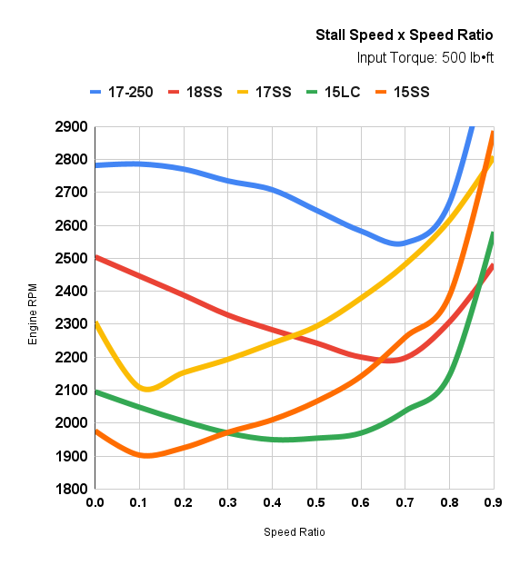
We are the only aftermarket torque converter manufacturer that has the equipment capable of testing for converter input torque, output torque, and dynamic torque. This data is critical in determining the stall speed, K-factor, and torque ratio of a given converter. This means we are the only manufacturer that can accurately give you this data for their torque converters, not just a guesswork figure based on incomplete data.
Our posted stall speeds are based on stock vehicles with an input torque of 500 lb•ft. Engine and other vehicle modifications will directly affect stall speed, including true, flash, and breakaway stall speed. All stall speeds are tested using our in-house dynamometer at a 0.0 speed ratio. All stall speeds, K-factors, and torque ratios are based on this 0.0 speed ratio.
Stall Speed: True stall speed is tested by putting the vehicle in drive and holding the throttle wide open while simultaneously holding the brake, so the vehicle remains stationary. When this happens, the torque converter will stall the engine at a certain RPM. When stalled, the engine will not be able to increase RPM until the vehicle is allowed to move. At this RPM, a true full stall is achieved. Do not test for true stall, as it can damage transmission shafts and overheat the torque converter. We have specialized equipment we use to perform this test. The stall speed of a converter is always dependent on engine torque.
Speed Ratio: A converter’s speed ratio can be calculated using the given RPM of a converter’s impeller and turbine. Speed ratio can be found using a simple equation. TURBINE RPM ÷ IMPELLER RPM = SPEED RATIO.
If a converter’s impeller is rotating at 2500 RPM, while its turbine is rotating at 1800 RPM, we would know the converter’s current speed ratio was 0.72. When the vehicle gets up to speed and the lock up clutch engages, the engine and impeller RPM will match the RPM of the turbine, resulting in a speed ratio of 1.0.
Torque Ratio: This number represents torque multiplication. For example, if a converter has a torque ratio of 1.8, then for every 100 lbs of input torque, the converter will deliver 180 lbs of output torque. The higher the torque ratio is, the better the vehicle’s towing ability will be. One way to think of it is to think of a vehicle slowly driving over a street curb. The higher the torque ratio is, the easier it will be to jump the curb.
K-Factor: K-factor is a mathematical equation used to calculate torque converter performance. A dynamometer that can read both input torque and output torque is used to determine K-factor. The K-factor can be found using a simple equation. ENGINE RPM ÷ √INPUT TORQUE = K-FACTOR.
This equation can also be used to find the stall speed. If a vehicle has an input torque of 500 lb•ft, its square root of input torque would be 22.36. If multiplied by a K-factor of 100, the vehicle’s stall speed would be 2236 RPM. Using the same torque converter, with a K-factor of 100, but changing the engine to produce 600 lb•ft of torque, the vehicle’s stall speed would be 2449 RPM. The equation would now read as: √600 × 100 = 2449. A general rule of thumb is to remember that the higher the K-factor is, the higher the engine RPM will be.
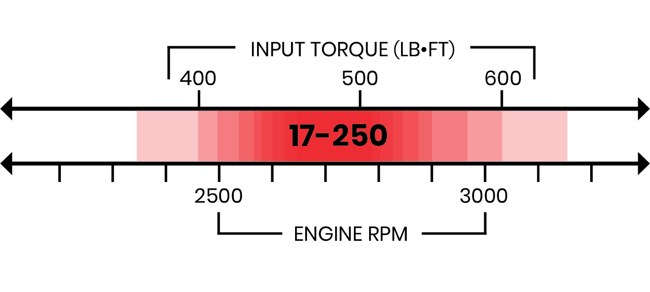
17-250: Will stall approximately 500 RPM above stock. The 17-250 is a high-stall torque converter. It's designed strictly for racing and sled pulling applications. The 17-250 is suitable for vehicles with large turbos and for situations where more engine RPM is required to get the turbo spooled. It helps maintain a higher RPM range for applications where turbo lag needs to be minimized.
Use With: Complete racing or sled pulling vehicles with large turbos.
Torque Ratio: 1.713
K-Factor: 124.4
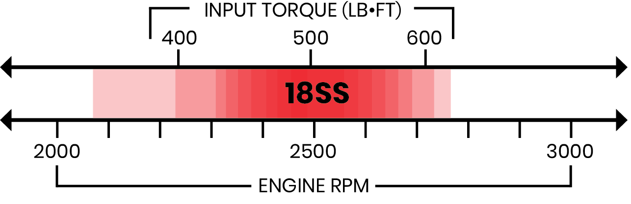
18SS: Will stall approximately 250 RPM above stock. The 18SS combines higher RPM stall characteristics and efficient coupling. This design enhances turbo spooling capabilities, making it particularly suitable for larger turbos that require higher RPM to reach efficiency. The 18SS works well for trucks occasionally used for racing or spirited driving while maintaining good street manners.
Use With: Street vehicles occasionally used for racing or spirited driving.
Torque Ratio: 1.671
K-Factor: 112.0
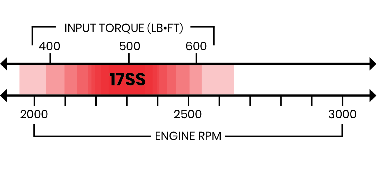
17SS: The 17SS is a complete stock stall option. It's an ideal stall for daily driving applications and is capable of handling light to medium towing and hauling duties, along with medium turbos. The 17SS is a practical upgrade for trucks without compromising any drivability.
Use With: Stock applications and daily drivers.
Torque Ratio: 1.756
K-Factor: 101.2
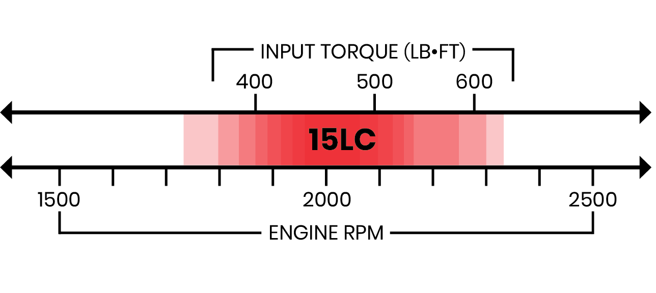
15LC: Will stall approximately 150 RPM lower than stock, and couples very efficiently as the converter’s speed ratio increases. The 15LC will increase coupling efficiency while running in a lower engine RPM range than a stock stall.
Use With: Daily driving trucks that may also moderately tow or haul. The 15LC can be used for lightly tuned trucks with larger single turbos also.
Torque Ratio: 1.790
K-Factor: 93.7
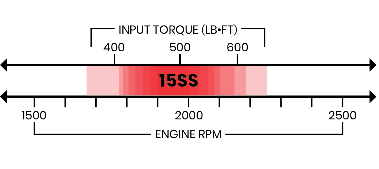
15SS: will stall approximately 300 RPM lower than stock. It has similar performance characteristics to a DA but will run at a lower engine RPM. This is a tighter feeling stall and will also couple at a lower RPM than stock stall. The 15SS maximizes low RPM pulling power, and an efficient stall like the 15SS will also help keep transmission temperatures lower.
Use With: Trucks that tow, haul, and work hard. The 15SS is best used with stock turbos and lightly tuned work trucks.
Torque Ratio: 1.798
K-Factor: 88.4
Details
- DTC-48RE
- DTC-48RE
- Goerend
- Current build time of 2-4 business days.
- New
Categories
Shipping Information
- Item Requires Shipping
- 78.0 lbs.
- W15.0000” x H15.0000” x L10.0000”