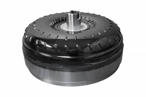
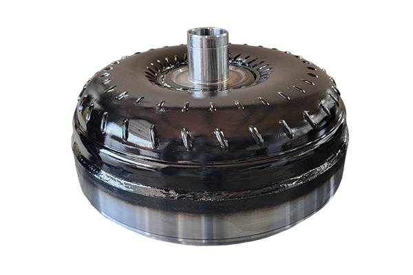
Triple Disc Torque Converter
Ford 5R110W
Description
Some of the first steps of designing new products is by identifying the weak points and problem areas of the existing parts and figuring out how to improve and fix them. In the case of the Ford 5R110W torque converter, the main factory components are the weak points. The impeller and turbine being made of thinner steel, and the lack of furnace brazing on the turbine, leaves these parts prone to breakage and catastrophic converter failures.
Rather than try to put a bandage on these weaknesses, Goerend sets the stock Ford torque converters aside and looked to the stronger, more reliable Allison 1000 torque converter. Using the Allison 1000 furnace brazed turbine and impeller, Goerend is able to produce the highest strength 5R110W torque converter.
Goerend Difference:
- Designed and manufactured in-house from start to finish
- K-factor and torque ratio tested on in-house dynamometer
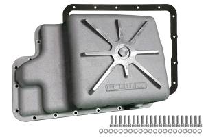
- Billet steel cover
- Made from steel forgings to reduce porosity
- Multi-bolt pattern
- Billet steel piston with complete damper assembly
- Insulates shock of crank pulses from rest of driveline
- Extends life of converter and transmission
- Made from steel forgings to reduce porosity
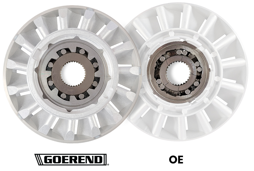
- Stator guaranteed to never break
- Designed to rotate better when going into coupling mode
- Creates a venturi effect to help torque multiplication
- Dual Torrington bearing stator design
- Lugged stator race prevents one-way roller clutch from so spinning out
- Patented internal design
- Insures lock up on computer and valve body signal
- Eliminates need to feather throttle to reach lock up
- Proprietary high-performance multi-disc lock up clutches
- TIG welded, furnace brazed, and silicon bronze reinforced turbine
- Below 0.005 blueprinted runout tolerances
- Blueprinted internal clearances
- Fully pressurized and leak tested
- Computerized robotic welding
- 4140 hardened turbine hub
- 4140 flanged impeller hub
- Accurately designed pilot
- Computerized balancing
5-Year Warranty:
5-Year Warranty is specifically limited to the torque converter purchased from Goerend. Warranty applies to any potential manufacturing defect inside the torque converter. Warranty does not cover any outside influences on the torque converter, or OEM stators. Warranty does not include loss of time, use, towing, installation, freight, or per diem damages. To transfer the warranty, invoice must be provided to Goerend. Warranty only valid through Goerend.
Articles
Videos
FAQ
Let’s start with two wall fans facing each other. If we turn one fan on, the wind from this fan will start make the other fan turn, although at a much slower rate than the "drive" fan.
In the case of a torque converter, the drive fan is connected to the engine, and the fan being “driven” is connected to the input shaft of the transmission. In addition, oil is used to transmit the energy between the two fans, as opposed to air in the example scenario.
When a vehicle is stationary, such as at a stop sign, with the transmission in gear and engine at idle, the drive fan that is connected to engine is spinning so slow that it will not transfer enough oil to turn the driven fan. As the vehicle’s brakes are let off and the throttle is held, the engine speed increases, and the drive fan blows more oil at the driven fan. The driven fan then starts to turn and move the vehicle. This important concept is commonly referred to as fluid coupling.
The drive fan will always turn slightly faster than the driven fan, just like the wall fans. If you were to stick a feather into the blades of the driven wall fan, the driven fan will slow down, but not the drive fan. In a real application, this is just like pulling a heavier trailer. The feather in the driven wall fan is essentially like adding a load to the vehicle.
What determines stall speed?
The two major things that determine the stall speed are engine torque and the torque converter.
This is one way to think about it: You’re on a stationary exercise bike that uses a fan for its pedal resistance. The smaller the fan is, the faster you can pedal. You may be able to pedal up to 200 RPM on the bike with a small fan, but only be able to pedal up to 50 RPM if you fit a bigger fan on the bike. The small fan was able to stall you at 200 RPM and the bigger fan stalled you at 50 RPM. Two different fans, two different stall speeds.
Now a professional athlete hops on the bike. With the big fan, they may be able to pedal 100 RPM, as opposed to your 50 RPM.
To compare this to the engine torque and torque converter, you must remember that a torque converter is nothing more than two fans. One fan is connected to the engine and the other fan is connected to the transmission. The fan connected to the engine blows oil at the fan connected to the transmission. Once the engine fan blows enough oil at the transmission fan, the transmission fan will start to rotate. The vehicle will then start to move.
Just like the exercise bike analogy, if you install a torque converter with bigger fan blades into a vehicle with the same engine torque, the stall speed will be lower. If you add more horsepower to the engine, just like the athlete hopping on the exercise bike, the stall speed will increase.
Now let’s talk about air. It's all about the oxygen. You’ll be able to pedal harder on the bike at sea level than on the top of a mountain because you’ll be able to breathe better, since there is more oxygen in the air. Similar to your lungs, an engine is nothing more than an air pump that uses fuel. The fuel an engine uses must react with oxygen in order to push the piston down and turn the crankshaft.
The higher the elevation, the less oxygen the engine has to work with, and the less fuel that can be injected to react with the oxygen. By using less fuel, it means the power input into the converter will be lower, resulting in a lower stall speed. Normally, the higher the elevation, the higher the stall speed that is needed in order to help offset the lack of oxygen that is present at sea level.
The engine turbo also can make a huge difference. Like the converter, the turbo is also a set of fans. The drive fan is located in the exhaust of the engine and it’s the exhaust flow makes this fan spin.
The driven fan of the turbo is connected to the drive fan and sits on the intake side of the engine. The driven forces oxygen into the engine so it can burn more fuel, resulting in more power.
A turbo with bigger fans takes longer to spool up and start to blow more air into the engine. Because of this, it takes longer to get oxygen into the engine cylinders to burn fuel. This is called turbo lag.
What is true, flash, and breakaway stall speed?
To explain stall speed, let’s start with a true full stall speed.
True stall speed is tested by putting the vehicle in drive and holding the throttle wide open while simultaneously holding the brake, so the vehicle remains stationary. When this happens, the torque converter will stall the engine at a certain RPM. When stalled, the engine will not be able to increase RPM until the vehicle is allowed to move. This is a true full stall. Do not test for true stall, as it can damage transmission shafts and overheat the torque converter. We have specialized equipment we use to perform this test.
The next stall speed is generally known as breakaway stall speed. A vehicle in drive is stopped on an incline and the throttle was held enough to hold the vehicle in place, but not enough to move the vehicle uphill. Once the throttle is held enough to start creeping the vehicle uphill, breakaway stall speed has been reached.
For example, if the engine RPM required to hold the truck is 1100 RPM, and an increase of 25 RPM started to move the truck, the breakaway stall speed would be 1125 RPM.
The last stall speed is generally known as flash stall speed. The flash stall speed takes effect under hard acceleration. A vehicle idling in drive and the throttle is then held wide open. The engine starts to accelerate quickly, then temporarily pause at an RPM as it starts to pull the vehicle.
If the engine took 1.5 seconds to get from an idle to 1500 RPM when floored, then took another two seconds to get from 1500 RPM to 2000 RPM, this would mean the flash stall speed would be 1500 RPM.
When we lower the stall of a converter, it can also lower the breakaway stall speed as well as the flash stall speed. Lowering the stall makes the engine work at a lower RPM for any given road speed and in most cases, will increase fuel mileage.
Lock Up & Speed Ratio
Once a vehicle gets up to speed there is a mechanism called a lock up clutch that locks the driven fan of the torque converter to its front cover, which is bolted to the engine. When this occurs, the drive fan and driven fan turn at the same RPM, with no loss of power in fluid coupling.
When the drive and driven fan are not locked together, heat is generated inside the converter. The greater the RPM difference between the drive and driven fan, the higher the temperature will reach. This heat is essentially lost power which results in a lower transmission life, performance, and fuel economy.
The loss of energy in this process can be calculated. A converter’s drive fan (impeller) may be turning at 2500 RPM and the driven fan (turbine) may be turning at 1800 RPM. By dividing the turbine RPM by the impeller RPM, we can find the efficiency of the converter, which is 72% at the given speeds of the impeller and turbine. This efficiency rate is also known as a converter’s speed ratio. When the vehicle gets up to speed and the lock up clutch engages, the engine and impeller RPM match the RPM of the turbine.
Low stall converters will be able to achieve a higher speed ratio before lock up. When low stall converters lock up, their RPM drop is substantially less, therefore easier on the converter’s clutch lining and will reduce clutch glazing. Because the fluid coupling of a low stall converter is more efficient, they are able to transfer more power, create less heat, and deliver better fuel economy than high stall converters.
Should I use a threadlocker on my torque converter bolts?
While you don't need to use a threadlocker, such as Loctite, on your torque converter bolts, we would recommend using Loctite Blue if you choose to use a threadlocker.
Why is my torque converter overheated?
Similar to how an engine produces heat that must be removed by the radiator and water pump, the torque converter generates heat within the transmission and relies on proper fluid flow for heat removal. Excessive line pressure with no line to cooler bypass may cause the torque converter and cooler to not receive adequate fluid flow. This leads to torque converter overheating, lock up clutch damage, which can then drag the engine down when the vehicle is stationary at idle. Replacing an overheated torque converter in this situation won't fix the underlying issue. The cooling circuit problem must be identified and resolved.
Stalls
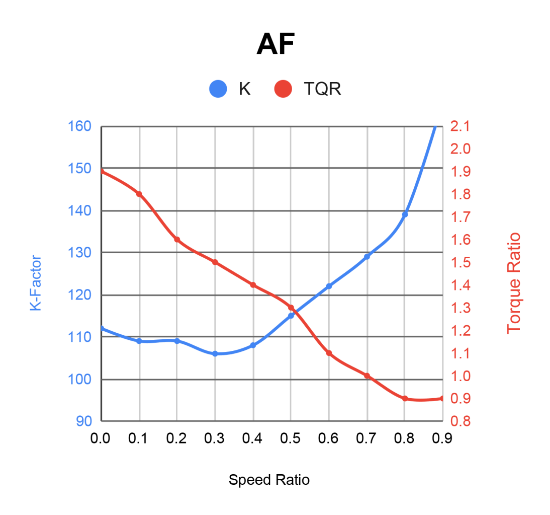
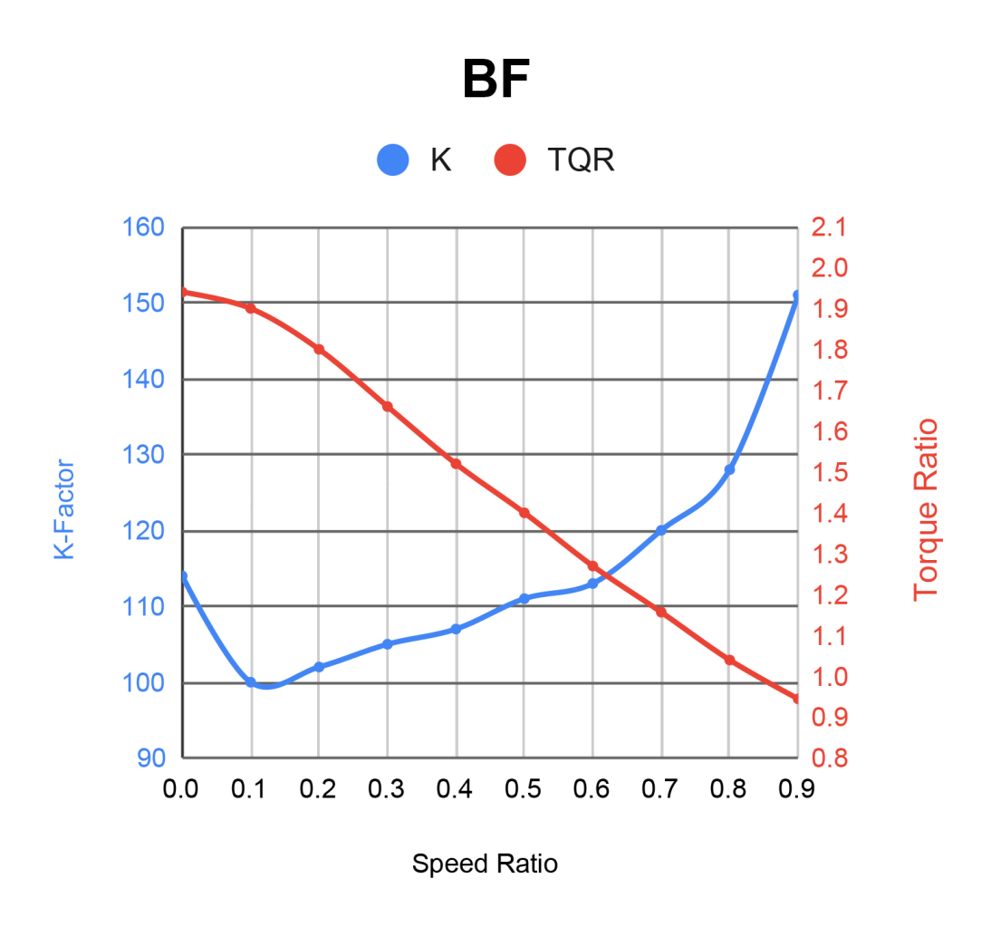
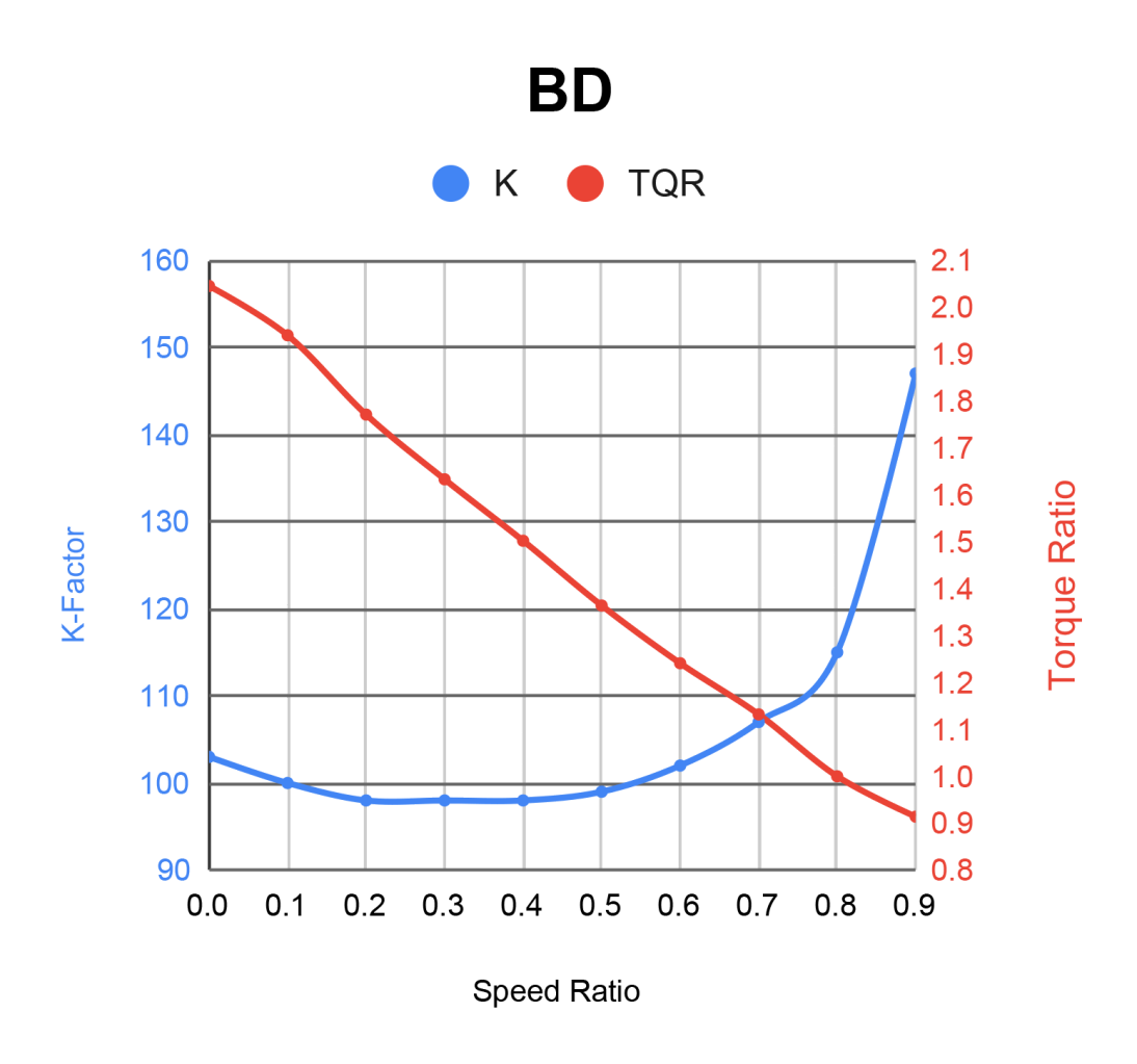
We are the only aftermarket torque converter manufacturer that has the equipment capable of testing for converter input torque, output torque, and dynamic torque. This data is critical in determining the stall speed, K-factor, and torque ratio of a given converter. This means we are the only manufacturer that can accurately give you this data for their torque converters, not just a guesswork figure based on incomplete data.
Our posted stall speeds are based on stock vehicles with an input torque of 500 lb•ft. Engine and other vehicle modifications will directly affect stall speed, including true, flash, and breakaway stall speed. All stall speeds are tested using our in-house dynamometer at a 0.0 speed ratio. All stall speeds, K-factors, and torque ratios are based on this 0.0 speed ratio.
Stall Speed: True stall speed is tested by putting the vehicle in drive and holding the throttle wide open while simultaneously holding the brake, so the vehicle remains stationary. When this happens, the torque converter will stall the engine at a certain RPM. When stalled, the engine will not be able to increase RPM until the vehicle is allowed to move. At this RPM, a true full stall is achieved. Do not test for true stall, as it can damage transmission shafts and overheat the torque converter. We have specialized equipment we use to perform this test. The stall speed of a converter is always dependent on engine torque.
Speed Ratio: A converter’s speed ratio can be calculated using the given RPM of a converter’s impeller and turbine. Speed ratio can be found using a simple equation. TURBINE RPM ÷ IMPELLER RPM = SPEED RATIO.
If a converter’s impeller is rotating at 2500 RPM, while its turbine is rotating at 1800 RPM, we would know the converter’s current speed ratio was 0.72. When the vehicle gets up to speed and the lock up clutch engages, the engine and impeller RPM will match the RPM of the turbine, resulting in a speed ratio of 1.0.
Torque Ratio: This number represents torque multiplication. For example, if a converter has a torque ratio of 1.8, then for every 100 lbs of input torque, the converter will deliver 180 lbs of output torque. The higher the torque ratio is, the better the vehicle’s towing ability will be. One way to think of it is to think of a vehicle slowly driving over a street curb. The higher the torque ratio is, the easier it will be to jump the curb.
K-Factor: K-factor is a mathematical equation used to calculate torque converter performance. A dynamometer that can read both input torque and output torque is used to determine K-factor. The K-factor can be found using a simple equation. ENGINE RPM ÷ √INPUT TORQUE = K-FACTOR.
This equation can also be used to find the stall speed. If a vehicle has an input torque of 500 lb•ft, its square root of input torque would be 22.36. If multiplied by a K-factor of 100, the vehicle’s stall speed would be 2236 RPM. Using the same torque converter, with a K-factor of 100, but changing the engine to produce 600 lb•ft of torque, the vehicle’s stall speed would be 2449 RPM. The equation would now read as: √600 × 100 = 2449. A general rule of thumb is to remember that the higher the K-factor is, the higher the engine RPM will be.


Details
- FTC-5R110W
- FTC-5R110W
- Goerend
- Current build time of 2-4 days.
- New
Categories
Shipping Information
- Item Requires Shipping
- 85.0 lbs.
- W15.0000” x H10.0000” x L15.0000”